Skylights for sandwich panels SPR-SKY & SPR-SKY ECO
Skylights for sandwich panels SPR-SKY & SPR-SKY ECO
Skylightss for sandwich panels SPR-SKY and SPR-SKY ECO are modern solutions designed to ensure maximum comfort for users of buildings with sandwich panel roofs. Both products provide access to natural daylight while reducing the need for artificial lighting and lowering operating costs.
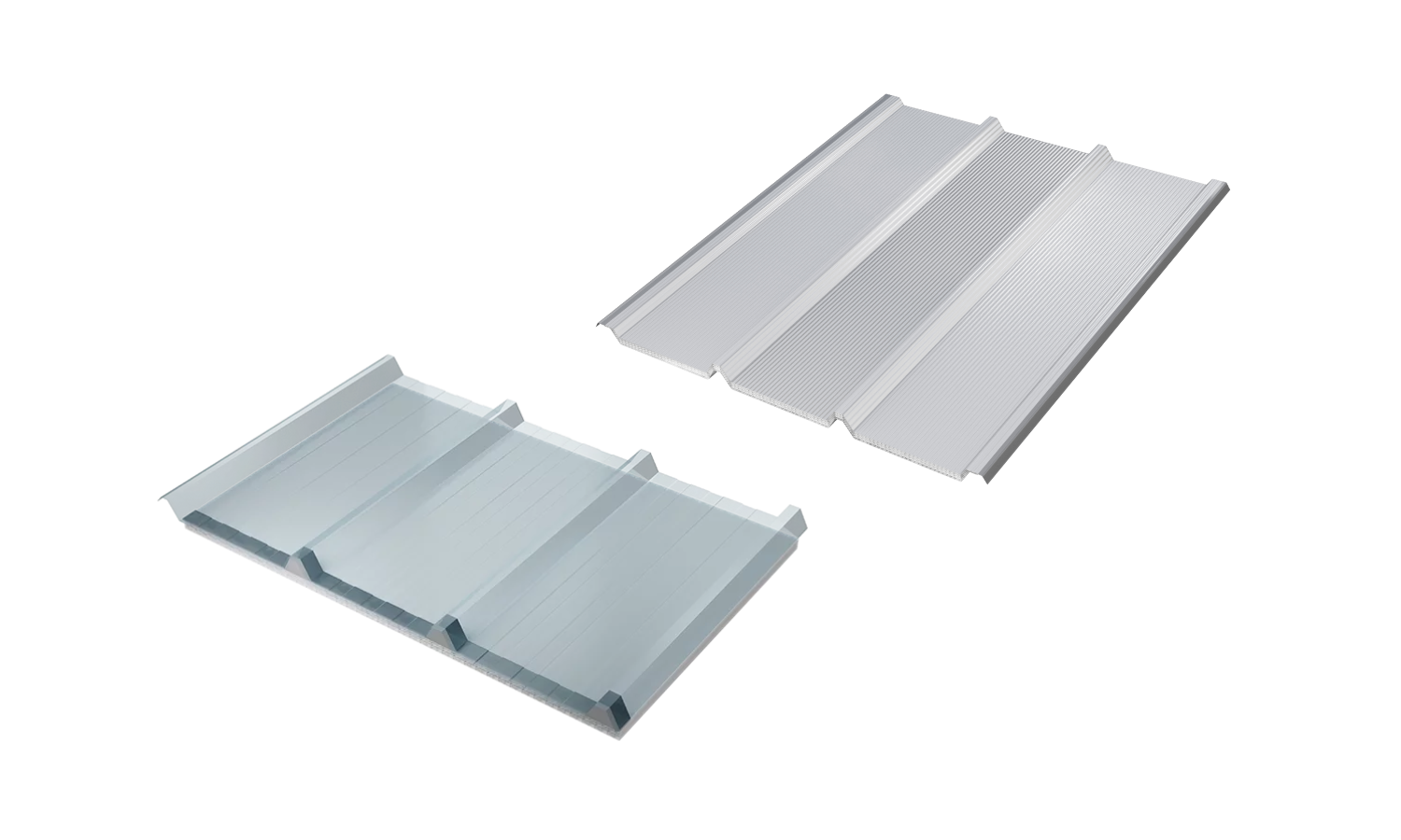
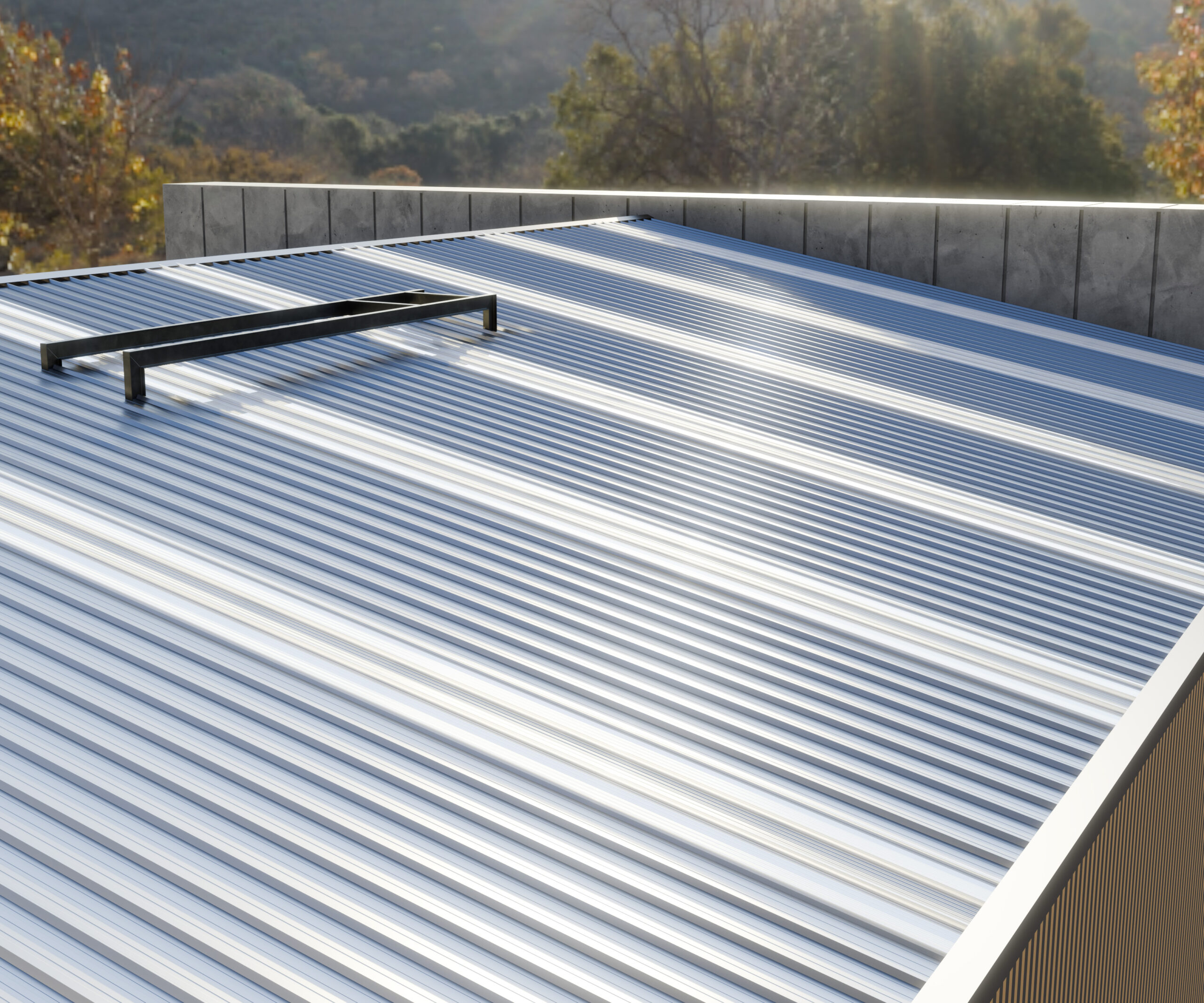
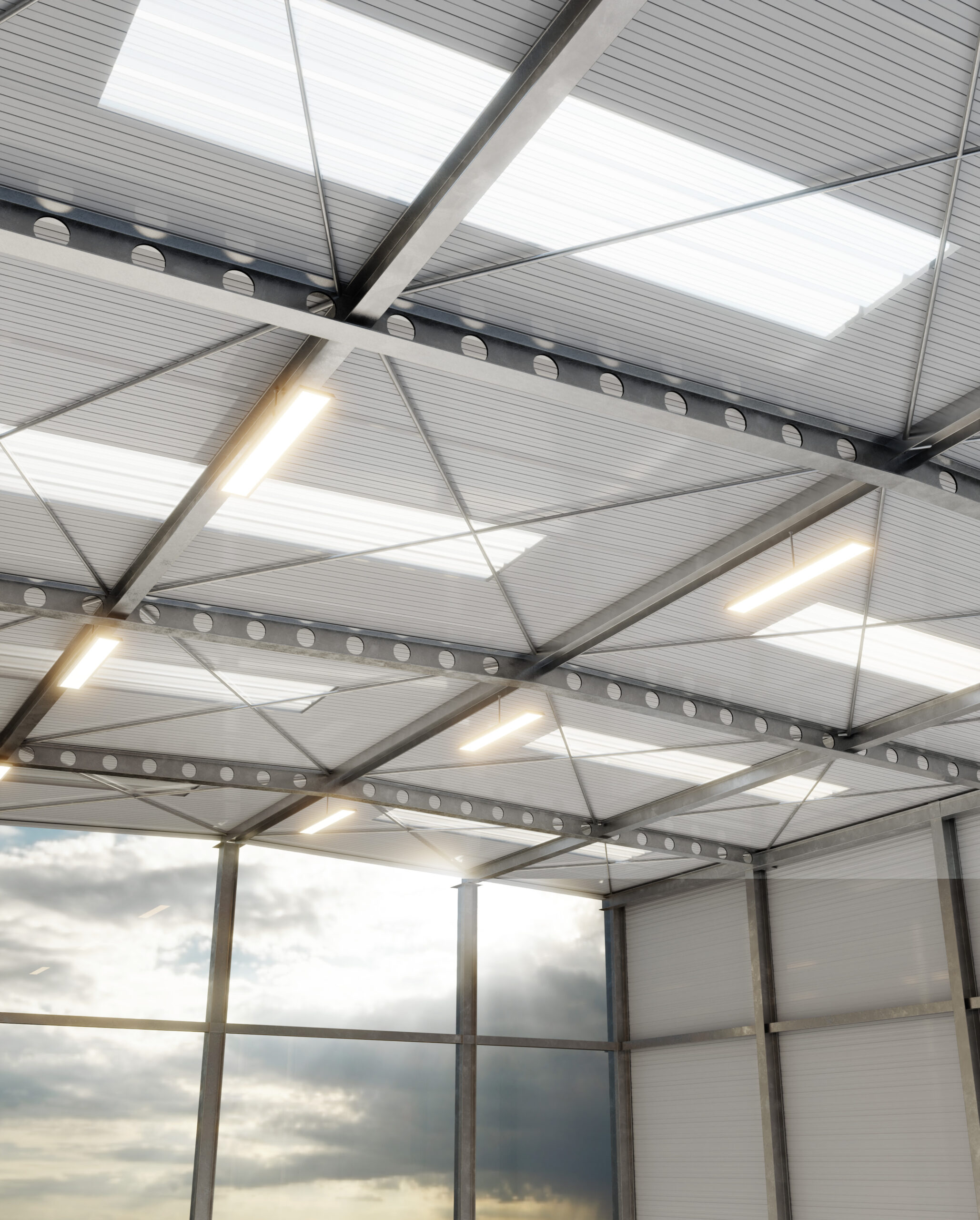
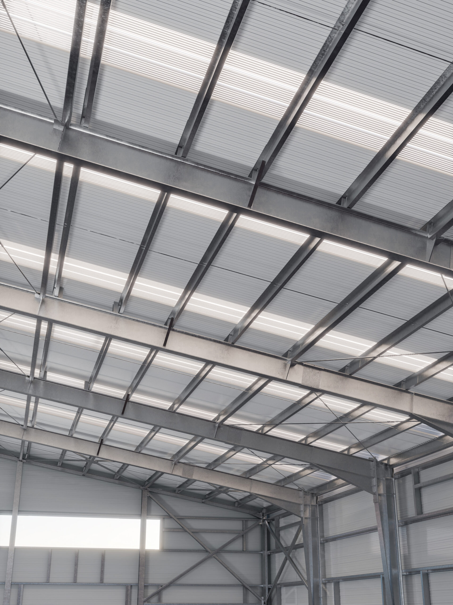
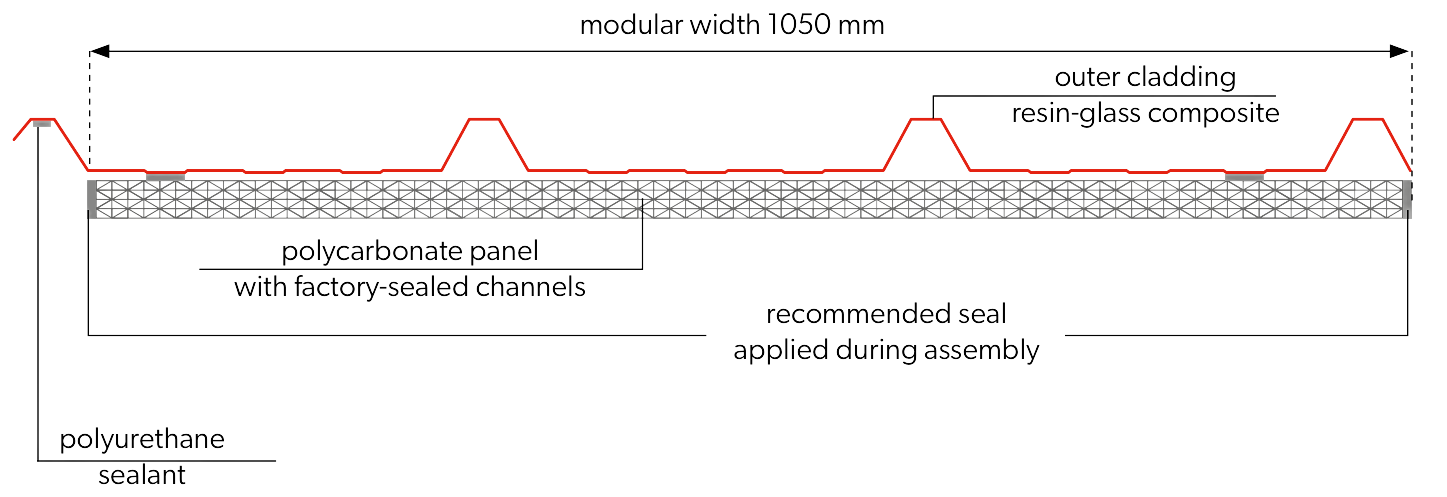
The application of the SPR-SKY rooflight is an effective solution for providing natural daylight inside a building. With roof coverage in the range of 7–15%, it can replace electric lighting. The multi-chamber structure of the rooflight limits excessive temperature increases caused by solar radiation while minimizing heat losses inside the building. Rooflights can be used in industrial facilities with pitched roofs (with a slope of more than 10%) in the form of warm covering with sandwich panels. The SPR-SKY rooflight can be installed as a point source of light or as a continuous skylight strip covering the roof from ridge to eaves, in the middle of the roof slope, near the ridge, or from the middle to the eaves. SPR-SKY rooflights connect to sandwich panels via side joints (on ridges) and end joints (overlaps), but the rooflight’s outer skin is 3–4 times thicker than the outer skin of the sandwich panel. This means that at overlap joints the claddings do not fit perfectly, so special attention must be paid to sealing during design and installation. It should also be remembered that rooflights are not as strong as the adjacent sandwich panel covering. Therefore, to ensure strength and tightness, installation must follow guidelines and good construction practice.
Application of the SPR-SKY ECO Skylight
The application of the SPR-SKY ECO rooflight is an effective solution for providing natural daylight inside a building. With roof coverage in the range of 7–15%, it can replace electric lighting. The multi-chamber structure of the rooflight limits excessive temperature increases caused by solar radiation while minimizing heat losses inside the building. Rooflights can be used in industrial facilities with pitched roofs, with the minimum roof slope being identical to that required for SPR CORE roof panels (not joined in length and without technological passages), i.e. 5%, in the form of warm covering with sandwich panels. The SPR-SKY ECO rooflight can be installed as a continuous skylight strip covering the roof from ridge to eaves. It should also be remembered that rooflights are not as strong as the adjacent sandwich panel covering. Therefore, to ensure strength and tightness, installation must follow guidelines and good construction practice.
Technical parameters of SPR-SKY
Material:
Fiberglass-resin composite combined with polycarbonate thickness 25 mm or 32 mm
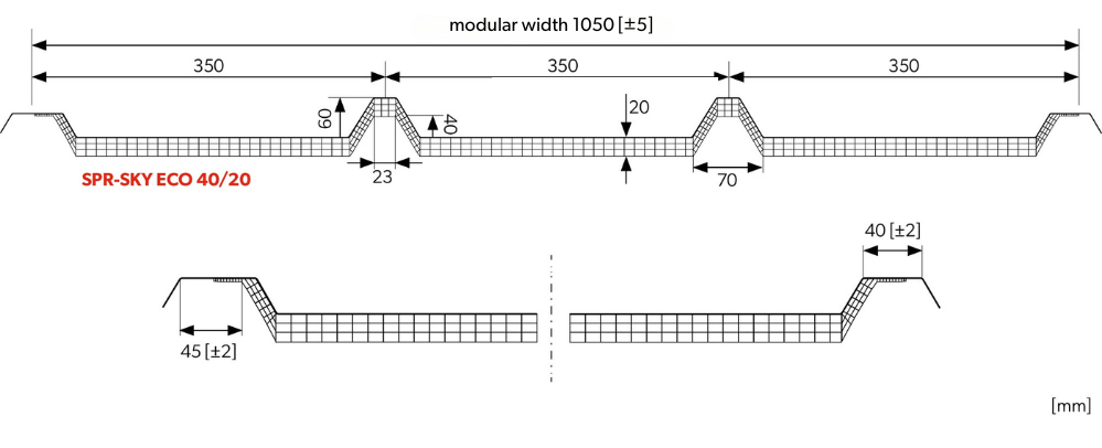
Modular width:
1050 mm
Opening light length:
7.0 m (maximum cladding length 7.2 m)
Joining of rooflights along the length is allowed directly on site
Recommended minimum roof slope:
10% (with 20 cm overlap)
Maximum support spacing:
1.5 m
Thickness:
Polycarbonate 25 mm – 30 mm + ridge height
Polycarbonate 32 mm – 35 mm + ridge height
Are you a roofer, distributor or designer? BP2 NEWS is not spam, it's a content-rich industry mailing - follow roofing trends and BP2's rapidly growing offerings with us!
 eProfil